Switching Quadratic Atlas Diagnostics
1. Purpose and Scope
This note documents what appears in the real quadratic parameter plane once an explicit orientation state is carried through the iteration and switching events are recorded as diagnostic observables. Escape-time colouring records coarse bounded-versus-escaping geometry. Orientation-sensitive diagnostics record internal history: flip count, flip parity, final orientation, first-flip iteration, and sector occupancy.
Emphasis is empirical. The objective is to define a concrete switching family, render diagnostic fields over a two-parameter plane, and identify recurrent morphological features that persist across multiple observables. A flip is an orientation change triggered by a threshold event during iteration; related notes provide diagnostic atlases and an interactive explorer for flip parity, first-flip time, and occupancy. The wedge, right-hand banding, and delayed first-flip contours are treated as primary targets. Mechanism is treated as a working hypothesis supported by diagnostic evidence, not as a completed derivation.
2. Baseline: the Real Quadratic Atlas
The baseline real quadratic family is
with real parameter . The standard atlas colours each parameter value by whether the orbit escapes beyond a threshold. This view records coarse stability, but it suppresses internal orientation history.
3. Model Definition: Orientation-Switching Quadratic Dynamics
The switching family evolves a real iterate together with a binary orientation variable :
Orientation is updated using a threshold-triggered flip rule,
The threshold depends on the initial-condition coordinate . The deformation parameter scales this threshold and changes switching itineraries across the parameter plane. A sign–sin switching variant is available in the interactive explorer as a comparison rule.
3.1. Fixed-Sign Reference Families
Two fixed-sign reference families provide a comparison ladder. These remove switching while keeping the quadratic skeleton.
Preserving sign:
Reversing sign:
The switching atlas is interpreted relative to these baselines rather than treated as a recolouring of one of them.
3.2. Deformation Values
Two deformation values organise the comparisons in this note:
- : baseline threshold-switching case (flip boundary at )
- : representative intermediate deformation
4. Diagnostic Invariants
The atlas is rendered through a family of diagnostic observables. Each observable is recorded for every grid point under fixed numerical settings (iteration cap, escape threshold, and step rules).
4.1. Escape Time
Escape time records the first iteration at which the orbit exceeds the escape radius.
4.2. Flip Count
Flip count records the total number of orientation changes before escape or truncation.
4.3. Flip Parity
Flip parity records whether the flip count is even or odd.
4.4. Final Orientation
Final orientation records , the terminal orientation state at escape or at the iteration cap.
4.5. First-Flip Iteration
First-flip iteration records the earliest step at which orientation changes. This diagnostic separates immediate switching from delayed switching and never-switch behaviour.
4.6. Occupancy Fractions
Occupancy fractions record the fraction of steps spent in and before escape or truncation.
5. Comparison Ladder
The ladder compares the two fixed-sign baselines against the threshold-switching atlas. This isolates morphology created by switching rather than by a static sign choice.
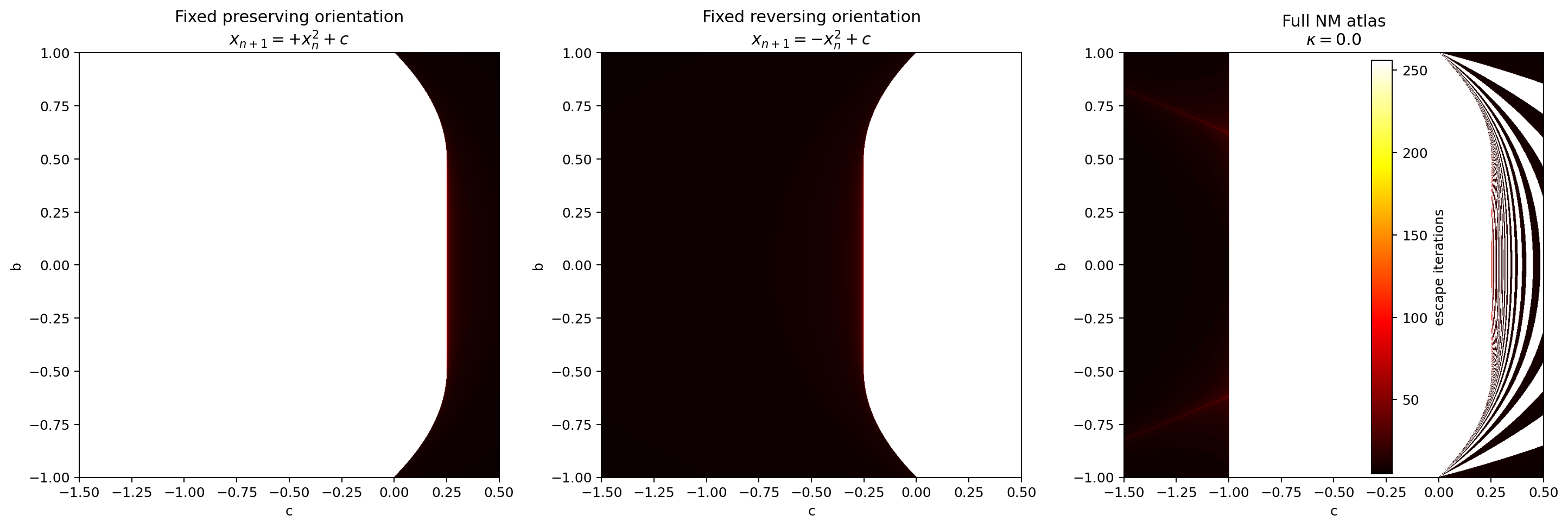
Figure 1: Comparison ladder at . Left: preserving sign . Centre: reversing sign . Right: threshold-switching atlas.
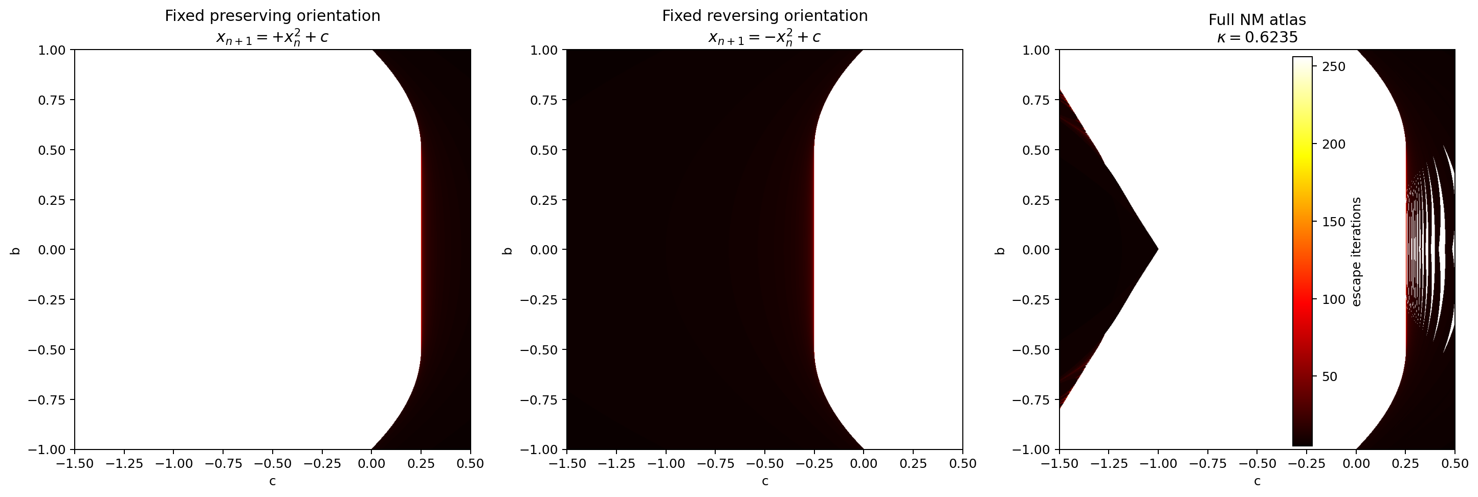
Figure 2: Comparison ladder at . The threshold-switching atlas develops a left-hand wedge and structured right-hand banding under deformation.
6. Flip Diagnostics
Flip diagnostics provide a direct view into switching history: how often switching occurs, whether it occurs early or late, and where the orbit lands in orientation space.
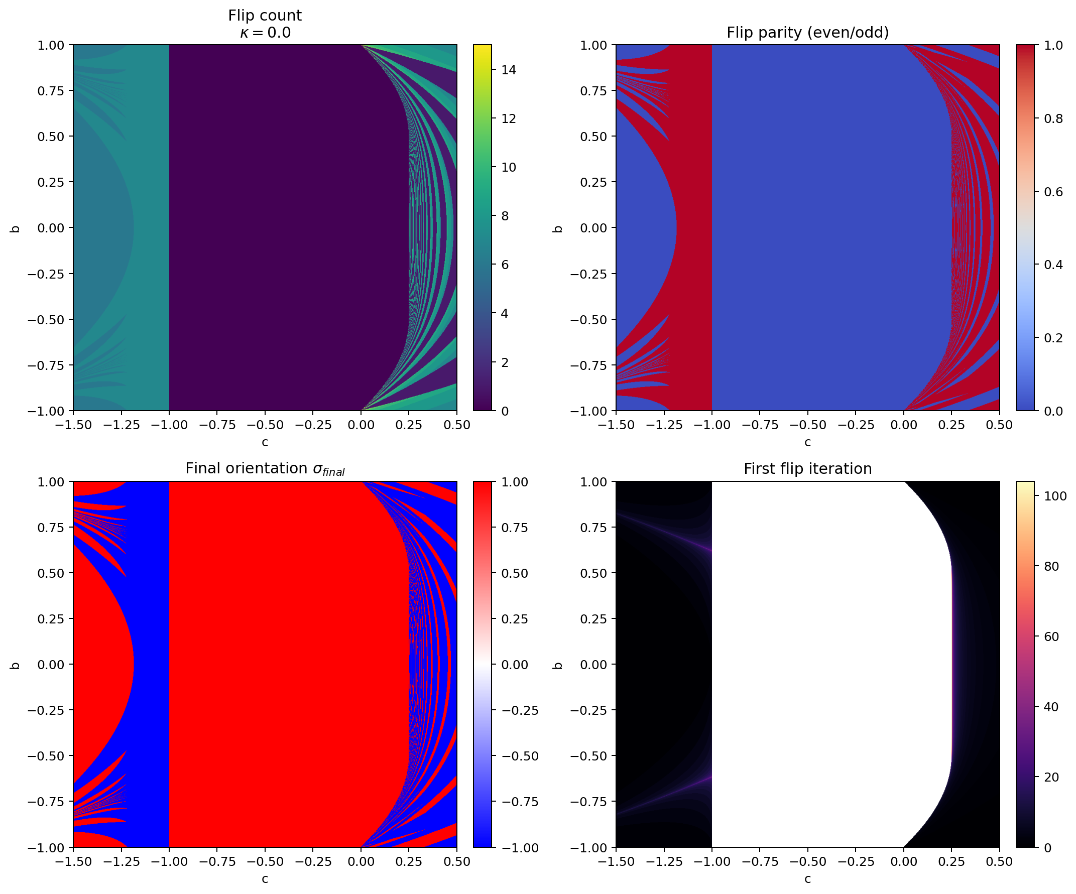
Figure 3: Flip diagnostics at : flip count, parity, final orientation, and first flip iteration.
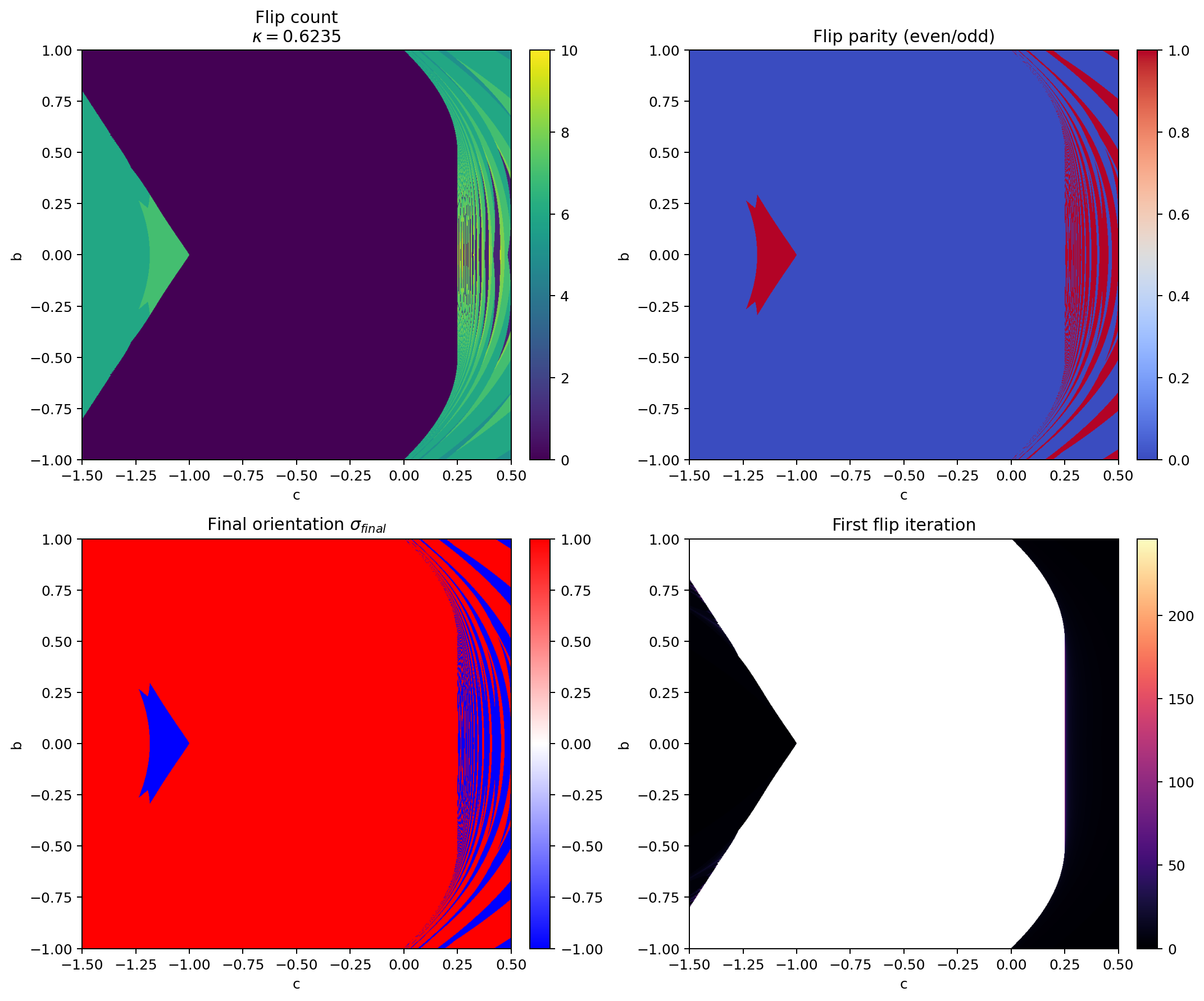
Figure 4: Flip diagnostics at . The wedge, right-hand switching domains, and delayed first-flip contours become sharply expressed.
6.1. First-Flip Contours as a Skeleton Diagnostic
The first-flip field is the most informative single panel. Broad regions correspond to immediate-switch or never-switch behaviour. Superimposed on this are contour families where switching is delayed by a specific number of iterations. These contours suggest an event-time organisation tied to when an orbit first exceeds the flip threshold.
7. Escape and Occupancy Diagnostics
Occupancy fractions complement flip count and first-flip iteration. Two points can share a similar escape-time colour and still spend very different proportions of time in each orientation sector.
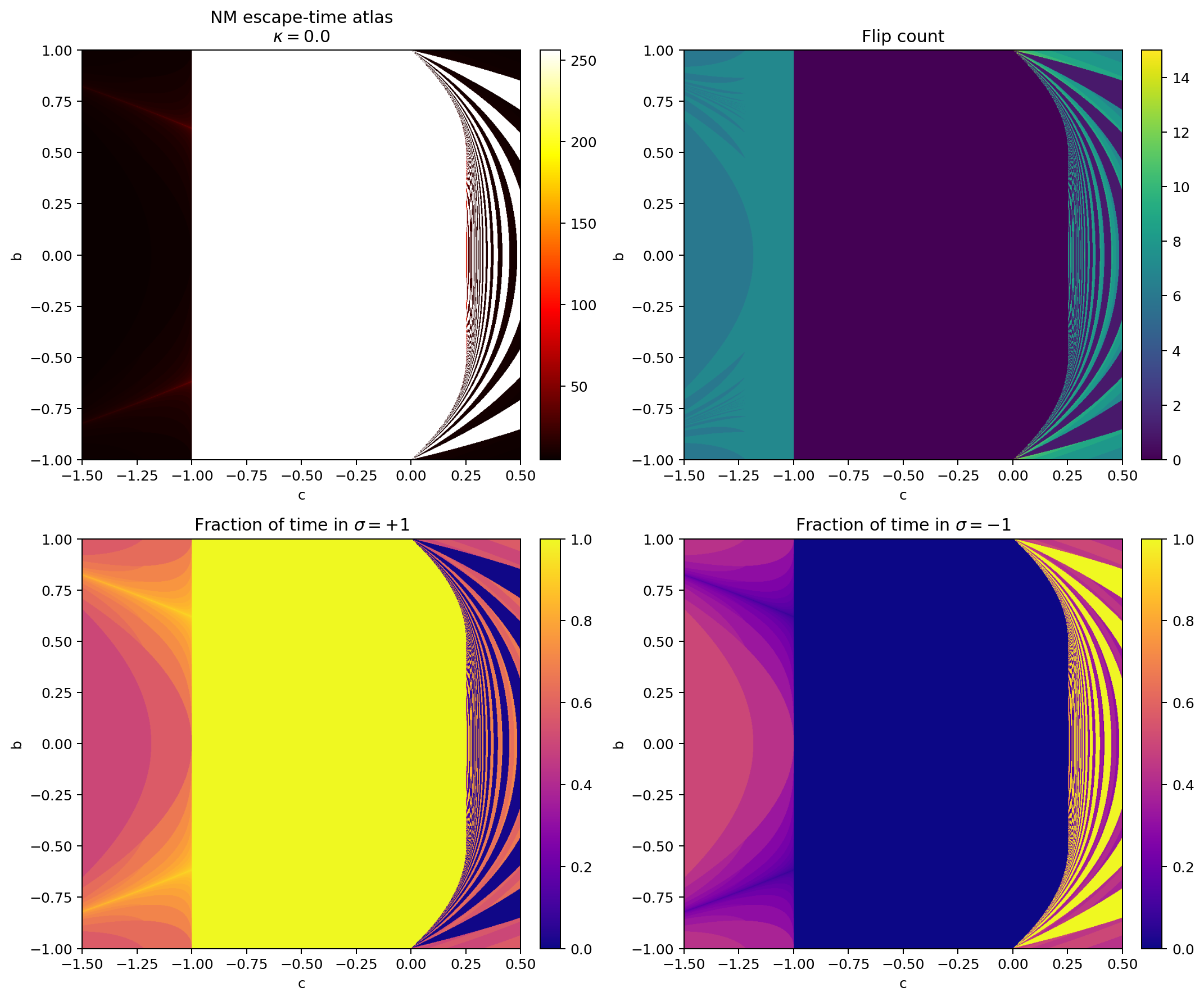
Figure 5: Escape-time and occupancy diagnostics at .
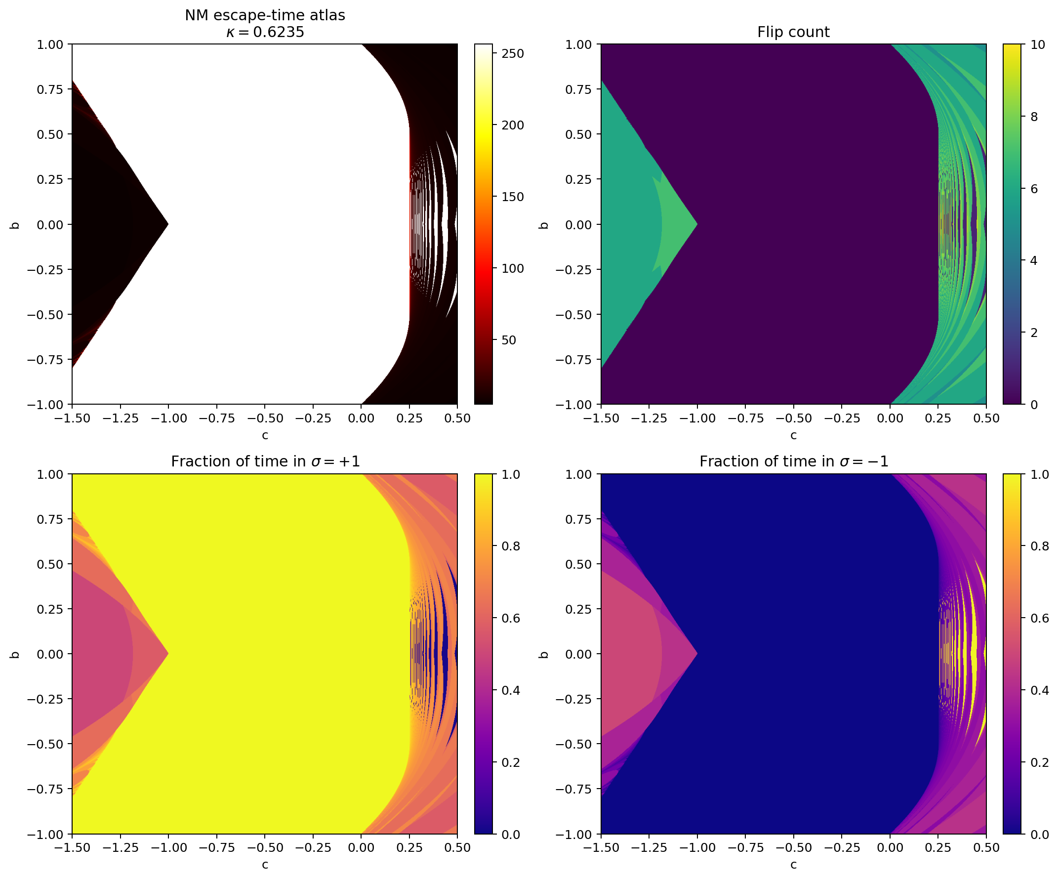
Figure 6: Escape-time and occupancy diagnostics at . Sector asymmetry becomes pronounced near the wedge and right-hand switching bands.
8. Morphology Results
Several recurrent structures persist across multiple diagnostics and respond systematically to deformation.
8.1. Left-Hand Wedge
The wedge appears in the switching atlas and sharpens under deformation. Its absence from the two fixed-sign baselines supports the interpretation that it is switching-generated rather than a static feature of the quadratic map.
8.2. Right-Hand Banding
Nested bands appear across escape time, flip count, parity, and occupancy. Persistence across multiple fields suggests structural partitioning rather than a colouring artefact.
8.3. Delayed First-Flip Contours
Fine contour families in the first-flip field suggest loci where the orbit remains below the flip threshold for several steps before exceeding it. These contours are mechanism-facing because they isolate a specific event time rather than a coarse lifetime.
9. Mechanism Hypothesis
A working hypothesis ties the morphology to a hitting-time / preimage skeleton of the flip boundary:
- Switching occurs when the next iterate crosses the flip boundary .
- The set of parameter values for which the first switch occurs at exactly step forms event-time curves in .
- Increasing raises the flip threshold for larger , changing the availability and timing of flips and producing the observed domain partitioning.
The first-flip field is the natural diagnostic for this hypothesis. A minimal drill-down samples a handful of points from (i) a wedge interior, (ii) a delayed-switch contour, and (iii) a right-hand band. The sequence plotted against iteration index tests for threshold boundary shadowing.
10. Robustness Checklist
Three numerical choices control appearance and require explicit reporting in any follow-up:
- grid resolution in
- iteration cap
- escape threshold
Morphology that persists under resolution refinement and iteration-cap extension is treated as structural. Morphology that shifts substantially under small numerical changes is treated as rendering-dependent.
11. Conclusion
Orientation-sensitive diagnostics define a usable extension of the real quadratic atlas. Flip count, parity, first-flip iteration, final orientation, and occupancy expose wedge structure, banding, and delayed-switch contours under threshold-triggered κ deformation. The first-flip field stands out as a mechanism-facing diagnostic and motivates targeted orbit-level drill-down and finer deformation sweeps.
12. Interactive Explorer
The explorer renders the same diagnostics over the same plane. The default switching rule is the threshold flip rule used for the figures below. A sign-sin rule is available via the dropdown as a comparison.
Model: with .
Further Reading


Code and Reproducibility
The analysis pipeline used in this study is implemented in Python. All code used to generate the figures and statistical results presented in this work is available as open-source software:
github.com/hasjack/OnGravity/tree/main/python/quadratic-atlas
This repository includes the full analysis pipeline, data ingestion routines, model fitting procedures, and scripts used to generate the figures presented in this paper.
Please consider funding this research on Research Hub

Content on this site is licensed under a Creative Commons Attribution 4.0 International License